The Razer Core Chroma X is currently listed by eGPU.io as the best rated external GPU enclosures available. It has power delivery, RGB built-in for the extra FPS and allows the potential of a single cable solution for eGPU, network, charging and peripherals. It’s also been relatively well documented however that the Ethernet socket on the enclosure has… dubious… support for Gigabit ethernet . Razer has stayed relatively quiet on the issue and while there are a few workarounds posted online , the best that I’ve achieved with these are that I can get the socket to work reliably at 100Mbps speeds, but not above.
Specifically the challenge is to achieve over 100Mbps network speeds without having a connection which regularly hangs or drops. Curiously, using the Razer dock, I experience the same issue with a USB 3.0 Ethernet dongle attached to the USB 3.0 ports on the enclosure and not just using the onboard RJ45 socket. This hints that the problem is not the Ethernet adapter itself but the chipset powering it. Suffice to say I tried weeks of driver fiddling and preference adjustments to get stability - no dice.
The mid term solution to this is that I’ve been daisy chaining a Lenovo Thunderbolt 3 dock (which itself contains Ethernet and USB, and handles power delivery) with the Razer enclosure (which then only houses the GPU). This totally works, but involves a huge mess of cable management and much more hardware on the desk than should really be necessary.
This was all until I saw this post on reddit describing how one user had replaced the stock USB/Ethernet riser with a 3rd party model and had some success. I set out to attempt the same effect, but do so in a way that didn’t involve having to have the chassis open the whole time…
DISCLAIMER: Following any of the steps from here yourself will definitely void any warranties you ever hope to claim on your unit, you’re also using power tools near power supplies which carries the risk of electrocution and of bodily injury. Don’t follow this as a guide - and if you do chose to attempt this yourself despite my warnings - make sure you’re confident with what you’re doing and you take appropriate safety precautions. You have been warned.
Pulling out the offender#
Removing the stock riser card from the unit is very simple. The Razer has a lovely pull-out tray design and the stock riser card is secured with a single torx screw. It has four USB 3.0 ports and an Ethernet socket on the side and a PCIe x4 connector on the base. The ports are offset at a very non-standard position compared to the mounting hardware - and this is undoubtedly a custom card designed specifically to save space in the enclosure.
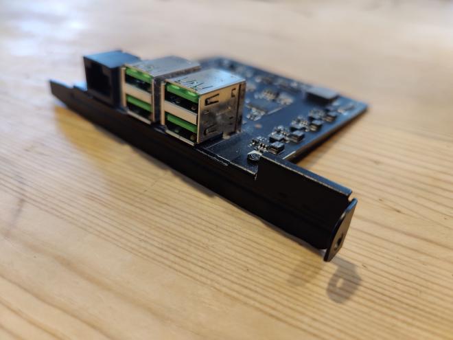
The nature of this custom card is that it’s going to be very unlikely to replace it with something else and get the ports to line up. This means whatever we do replace it with is going to have to expose it’s ports to the outside world in some other way. The very narrow space available for it also won’t fit a standard size PCIe card without getting in the way of your GPU - so we’re also going to need to find a different place to mount the riser card too.
The original post which inspired this mod has a solution to the latter problem (using a PCIe riser cable - which I’ve also done) but not the latter. Given the tray design of the Razer, I feel like there are only three options:
- Somehow mount a rise card near the back of the tray unit, up against the mesh and cut away the mesh to expose them. The locking mechanism for the tray is unfortunately right in the way to make this feasible unless the card is very small.
- Use the original port “holes”, but pass cables through them. This would work for the cables, but the original holes aren’t big enough to pass full USB or RJ45 connectors through. Custom cables, constructed “in-situ” could work, but this feels like a world of pain - especially if we want to ensure high data transfer rates down these cables.
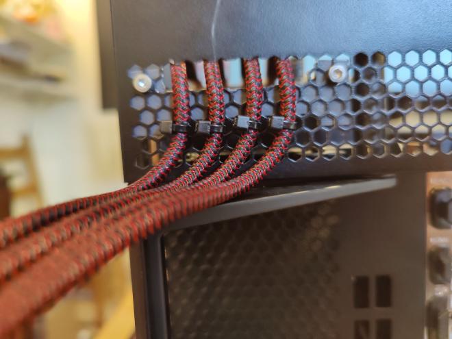
- Cut new holes, for pass-through cables, but don’t try and mount the ports near the back. This the route I went for, opting for 4x 20cm USB 3.0 Male to Female extension cables.
But what about Ethernet?#
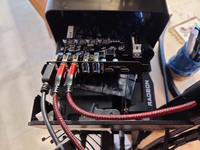
The riser card mentioned in the original post was a Startech card which currently retails for £52 in the UK. Having already purchased a Gigabit Ethernet USB3.0 dongle , from previous testing, combined with the earlier hypothesis that the problem wasn’t the Ethernet adapter itself, but the USB host it was attached to, I took a gamble on only going for an USB 3.0 riser board, but one that offered several more USB 3.0 ports to play with. In theory a fully supported USB3.0 port should enable easily enough bandwidth to drive Gigabit Ethernet without needing an onboard controller directly on the PCIe bus. This has the advantage of also giving a much wider range of options, both in design and price. I opted for a highly reviewed option on amazon , priced at ~£30.
My initial plan was to then have the dongle hanging out the back of the razer alongside a selection of USB3.0 extensions, however due to the relatively short cable length on the dongle, I eventually opted to have that on an extension too; and take the added design freedom that gave for board mounting positions.
On receiving the parts, I test fitted the PCIe riser and USB3.0 card with the Ethernet dongle, powered things up and ran for a few hours to check network speed and stability. The card performed EXCELLENTLY, with Gigabit performance and no connectivity drops. This test fit however does require running the unit with the case open and cables hanging out. Fine for testing - but not pretty (or very safe).
NOTE: If you are following along at home - I very much advise doing a test fit here and making sure everything works before starting to cut holes in your case for the cables. We’re about to hit the point of no return.
Cutting holes#
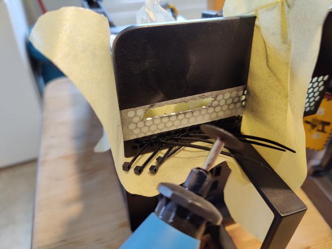
After verifying the functionality of the setup, I 3d printed some brackets and cut some holes. Conveniently, the hexagonal mesh on the rear is also the perfect size to use as mounting holes for M3 socket screws - so I designed around using these as mount points. The plan would then be to remove “2-hex-high” section of mesh which would leave a ~8mm high gap, high enough to pass a standard size usb connector through.
The mesh is made of powder coated steel and so is going to be difficult to cut with hand tools - I opted for a dremel-style tool - taping up as much of the surrounding area to constrain as much of the produced metal dust as possible. I do not want conductive metal dust in a GPU or a PSU - both could be very danger. You also don’t want it in your lungs or eyes so wear proper PPE.
Mounting Brackets#
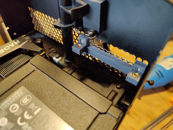
I opted for a two-part print for the mounting brackets - mostly for print orientation. The first which attaches directly to the case and provides a horizontal mounting point for the other part - intentionally level with the top of the PSU. The second which directly holds the board. That latter part also took several attempts to get in just the right position to allow the cables to line up well with the hole cut in the mesh. I’m not currently planning on releasing the CAD files for this, partly because they will only be valid for a given combination of PCIe card and extension cables and also because if you’re not comfortable designing and printing your own brackets - this mod probably isn’t for you. One thing I would however advise if you are designing your own would be the use of brass threaded inserts - both for the case mounting screws and for the board mounting points. I used M3x5 screws throughout, and getting short screws like that to grip effectively just within the printed part on a friction fit would be a potentially tall order. The metal threads however provided great purchase.
Putting it all together#
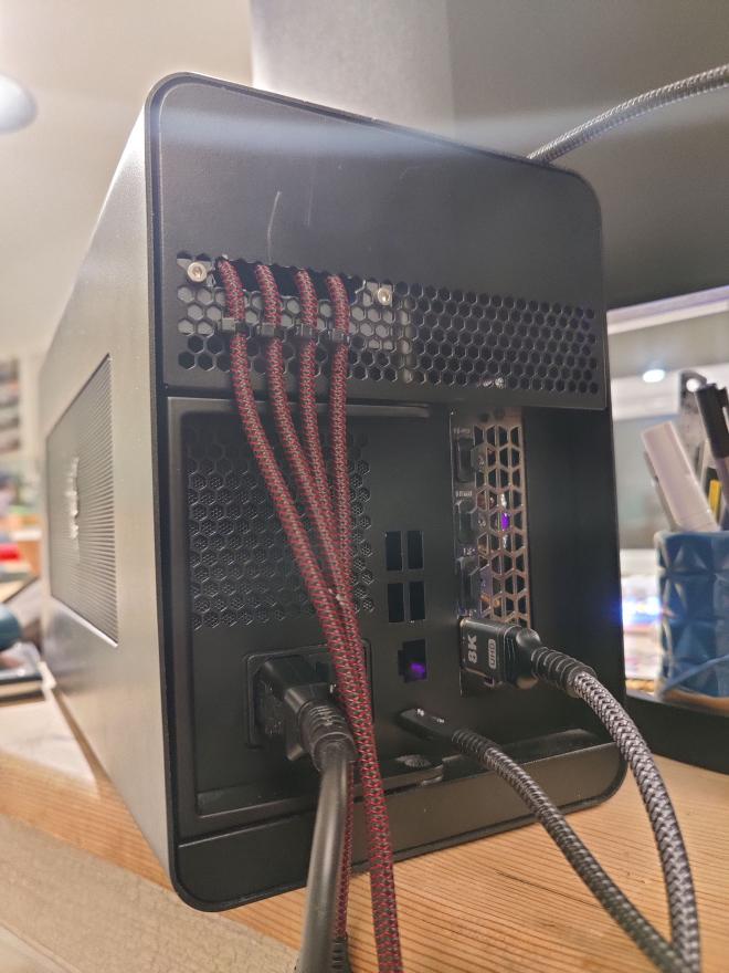
With the card mounted on the final mounts and all the cable holes cut it was time to reassemble and test. As a final assembly step I cable tied the USB extension leads which come out of the case to the hex-mesh, initially for tidiness - but more importantly, this prevents movements in the cables from flexing the position of the riser card and the PCIe riser cable - both of which are more fragile (and expensive) than the USB cables themselves. I initially made the mistake of cable tying them too low which then blocked the movement of the locking mechanism handle below. On a second attempt, cable tying higher worked perfectly.
What next?#
For now, 4x USB 3.0 A ports is sufficient for my setup. Once combined with the inbuilt lower speed USB hubs built into peripherals (like monitors etc…), that’s plenty. However there are a further 1x USB 3.0 type A and 2x USB 3.0 type C ports unused on the card which could easily be exposed in the same way. The latter of those notably supporting higher power delivery levels which could be useful. There’s a watchout here that standard 1x PCIe slots can only deliver up to 25W of power (assuming that the Razer can drive the card that high in the first place), which doesn’t give much power delivery budget to be used by devices. Given the power delivery budget challenge I think it’s unlikely I’ll resort to the type C ports for power reasons and so the USB A ports will do just fine.
Beyond that - cable management! I’m building a new desk at the moment (which I’ll come to in a separate post) - but once that’s sorted then getting all the cables sorted will be the next job. I can also finally sell on the Lenovo TB3 dock!