I used to think that good cable management was a luxury, something that wasn’t worth spending time on. The I realised that the back of the printer looked like this:
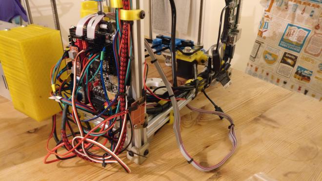
This doesn’t look great, but more importantly, since the upgrade to the Bigtreetech SKR 1.3 [32bit board, can highly recommend], all of my stepper cables which ended in standard dupont connectors, were fitting into JST XH connector sockets. This works, but only as long as you don’t jog them too much. What was happening slightly too often was that the leads were partially falling out and causing a very evil noise to come from the motors.
“The best time to plant a tree was 20 years ago. The second best time is now.”
-– Chinese Proverb
The time had come for a better solution.
Armed with a fresh pack of cable ties, some fresh cables, a multipack of JST XH connectors and critically the right crimping tool [NB: This is not the same crimping tool as the dupont connectors, whatever they claim], I set about rewiring most of the whole printer. Here’s what I learned in the process.
- Learn to crimp properly. I thought I knew. I did not. This video was a great starter: https://www.youtube.com/watch?v=iHm2yNMxj2s
- Work out your cable routing before cutting anything. Ideally your cable routing should follow a common pattern. In my case cables go left, then down, then back. The only exception is cables that start in the rop right, which can’t go left first, so they go back then left, then down.
- Have sufficient cable clamps (or some other way of attaching the cables to the frame), before you start. Once you start rewiring, you can’t print more… because your printer has all it’s wires on the floor. I use my 2020 extrusion clamps , mostly the 8mm ones.
- Get something to label your cables. You can see in the cover photo I used the EC style numbered clips, but during the wiring I also had coloured bullclips and a selection of other clips to keep track of which wires were which. Especially if you try at do a twisted cable loom where all of the cables are twisted together, it’s really important to remember which is which at the end.
- Start at the ends and work toward the centre. I started with each of the steppers or sensors and worked slowly inwards, with the cable loom getting slowly thicker at each stage and finally reaching the control board. Partly this was because I was waiting for the right crimping tool to arrive, but this also meant I had time to plot the most complicated part once I knew more about the constraints I was working with and had already made the mistakes I was going to make along the way. By not attaching the the terminal connectors on the end of each cable until the very end, I kept the maximum flexibility for precisely how I wanted to route the cables until everything else was in place.
- Leave plenty of spare length in your cables. It’s much easier to cut more off, than it is to solder more on. I didn’t get this perfect, and I did solder on a few more sections to make up some extra length where I got this wrong, but those extra sections took significantly more time to strip, solder and then cover than just trimming the longer wires.
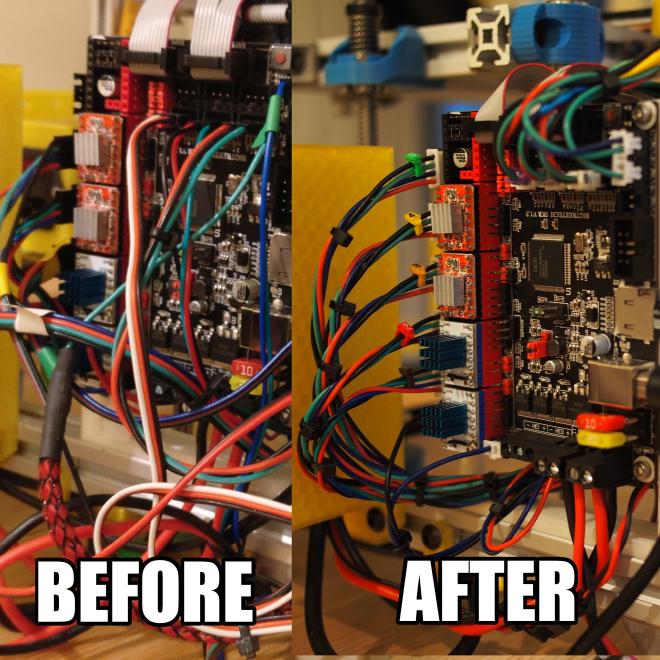
In the end the comparison was pretty stark.
Not only do my cables now not fall out, but they’re also much tidier and I think also much safer against being caught against other things moving around.
On a personal note, it’s also a very therapeutic task for a quiet weekend day, which I can very highly recommend for a bit of time to recharge. On which note, I’ll leave you with some cable porn…